Daily QA CBCT Calculations

The goal is to determine how closely a bb in a phantom is aligned with the plan isocenter.

Calculations

The first step is to determine the bb's location within the CBCT volume. A 3D volume is constructed, and a VOI (volume of interest is searched for the bb. The reasons for limiting the search volume are:

All possible sub-volumes of the VOI are searched of size 4*4*2 (X*Y*Z) voxels. The sub-volume with the largest sum of voxel values is assumed to be a coarse location for the bb.

Next, a sub-volume is taken that is slightly larger than the actual size of the bb (the size of the bb is a configuration value) centered on the coarse location. The sub-volume is summed across the 3 different axis to create 3 one-dimensional arrays. The profile of each array is analyzed with a center of mass algorithm to determine the exact center of the bb in each dimension. As a further check, the magnitude of the 'bump' in each profile created by the bb is checked to ensure that it is above a given number (configured value) of standard deviations to reject random image noise.

Given the bb's location in pixels $pix_X, pix_Y, pix_Z$, the location is converted to the frame of reference $for_X, for_Y, for_Z$ in mm by multiplying the X and Y coordinates by the PixelSpacing for X and Y, and the Z coordinate by the SliceThickness . The result is offset by the ImagePositionPatient from the slice with the lowest Z coordinate value: $$for_X = pix_X \times PixelSpacing_X + ImagePositionPatient_X$$ $$for_Y = pix_Y \times PixelSpacing_Y + ImagePositionPatient_Y$$ $$for_Z = pix_Z \times SliceThickness + ImagePositionPatient_Z$$
  • 0028,0030 PixelSpacing : Physical distance in the patient between the center of each pixel, specified by a numeric pair - adjacent row spacing (delimiter) adjacent column spacing in mm
  • 0018,0050 SliceThickness : Nominal slice thickness, in mm.
  • 0020,0032 ImagePositionPatient : The x, y, and z coordinates of the upper left hand corner (center of the first voxel transmitted) of the image, in mm.

The coordinates in mm are then translated to the RTPLAN frame of reference. To do this, a DICOM REG file is found (note the DICOM uses a UID, aka unique id, to identify frames of reference) that references both the CBCT's frame of reference and the RTPLAN's frame of reference as shown in the diagram below.

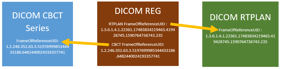
Standard linear algebra is used to multiply the vector by the $4\times4$ matrix contained in the DICOM REG file as FrameOfReferenceTransformationMatrix . The resulting vector is the bb's $X,Y,Z$ location in the RTPLAN's frame of reference. The RTPLAN IsocenterPosition is subtracted from the result to get the error between CBCT and isocenter: $$X_{error} = X_{CBCT} - X_{PLAN}$$ $$Y_{error} = Y_{CBCT} - Y_{PLAN}$$ $$Z_{error} = Z_{CBCT} - Z_{PLAN}$$

DICOM attributes used to map the CBCT's frame of reference to the RTPLAN's frame of reference:
  • 0020,0052 FrameOfReferenceUID : The Frame of Reference UID shall be used to uniquely identify a Frame of Reference for a Series.

  • 3006,00C6 FrameOfReferenceTransformationMatrix : The Frame of Reference Transformation Matrix (in the REG file) describes how to transform a point (Bx,By,Bz) into (Ax,Ay,Az) according to the equation below (For REG files this is the RTPLAN FrameOfReference ):

  • 0070,0308 RegistrationSequence : A Sequence of registration Items. Each Item defines a spatial registration of the images referenced in that Item to the Registered RCS established by this SOP Instance. All referenced images are in the same spatial\ Frame of Reference or atlas. This sequence contains the CBCT FrameOfReference .

  • 300A,012C IsocenterPosition : Isocenter coordinates (x,y,z) in the Patient-Based Coordinate System. (from the RTPLAN file)

There is a special case where the CBCT has the same frame of reference as the RTPLAN, and no matrix transformation is necessary. While the analysis will be performed, the results may or may not be useful. In practice this should not occur, but the software does support it.

Example CBCT Calculations

Input Data

The following values were taken from actual machine values:


PixelSpacing : 0.51119 \ 0.51119
SliceThickness : 1.98972453680719
coarse location in voxels: 276, 239, 49 (calculated from volume)
fine location in voxels: 275.863, 238.8094845, 48.478 (calculated from volume)
ImagePositionPatient of first slice: -130.2839, -130.70374936618, -91.855446207549
FrameOfReferenceTransformationMatrix : $$ \left[ \begin{array}{cccc} 0.999994& -0.000017& 0.003545& -6.006019\\ 0.000021& 0.999999& -0.001028& 171.213262\\ -0.003545& 0.001028& 0.999993& 59.937419\\ 1.0& 0.000000& 0.000000& 1.000000 \end{array} \right] $$
IsocenterPosition : 4.221317, 162.6656, 64.92423


Calculations

Determine coordinates of bb in CBCT frame of reference in mm: $$ X = 275.863 \times 0.51119 + -130.2839 = 10.7349192 $$ $$ Y = 238.8094845 \times 0.51119 + -130.70374936618 = -8.6265526 $$ $$ Z = 48.478 \times 1.98972453680719 + -91.855446207549 = 4.6017616 $$

Transform with matrix to RTPLAN coordinates: $$ \left[ \begin{array}{c} 10.7349192\\ -8.6265526\\ 4.6017616\\ 0 \end{array} \right] \times \left[ \begin{array}{cccc} 0.999994& -0.000017& 0.003545& -6.006019\\ 0.000021& 0.999999& -0.001028& 171.213262\\ -0.003545& 0.001028& 0.999993& 59.937419\\ 1.0& 0.000000& 0.000000& 1.000000 \end{array} \right] = \left[ \begin{array}{c} 4.745294\\ 162.582208\\ 64.492228\\ 1.0 \end{array} \right] $$ Subtract the RTPLAN isocenter from the CBCT coordinates to determine the error: $$ X_{error} = 4.745294 - 4.221317 = 0.52398 $$ $$ Y_{error} = 162.582208 - 162.6656 = 0.083384 $$ $$ Z_{error} = 64.492228 - 64.92423 = -0.43202 $$