Edges measurement is used by multiple tests, including Collimator Centering and Collimator Position
Generally, sets of four edges of a rectangle are found, as shown in example below:
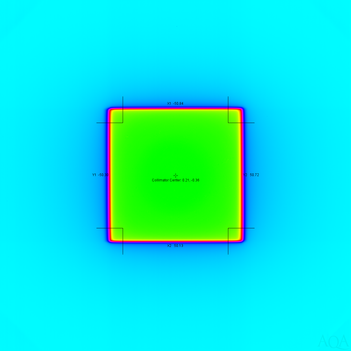
The first step is to use the associated RTPLAN to determine the expected position and length of the edge. As an example, consider the left in the image above. The horizontal position is given by the RTPLAN, and the expected vertical length is given by top and bottom edges.
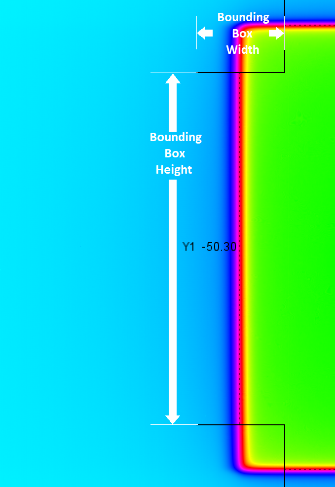
Given the expected position, a bounding box is created, using the penumbra width. The penumbra width is defined as the configuration value PenumbraThickness_mm . For the left edge, the bounding box is centered horizontally around the the expected position, and the width is the penumbra width.
To improve the accuracy of the measurement of the left edge, interference from the intersecting top and bottom edges must be removed. This is done by limiting the top and bottom of the bounding box by 1/2 the penumbra width from the top and bottom edges.
The bounding box is indicated by the black lines, and annotated in the detail below with the white lines and arrows.
A profile of the edge is then created by summing each column of pixel. In the case of a horizontal edge, the rows would be summed. The resulting profile is then smoothed using a cubic spline as shown below:
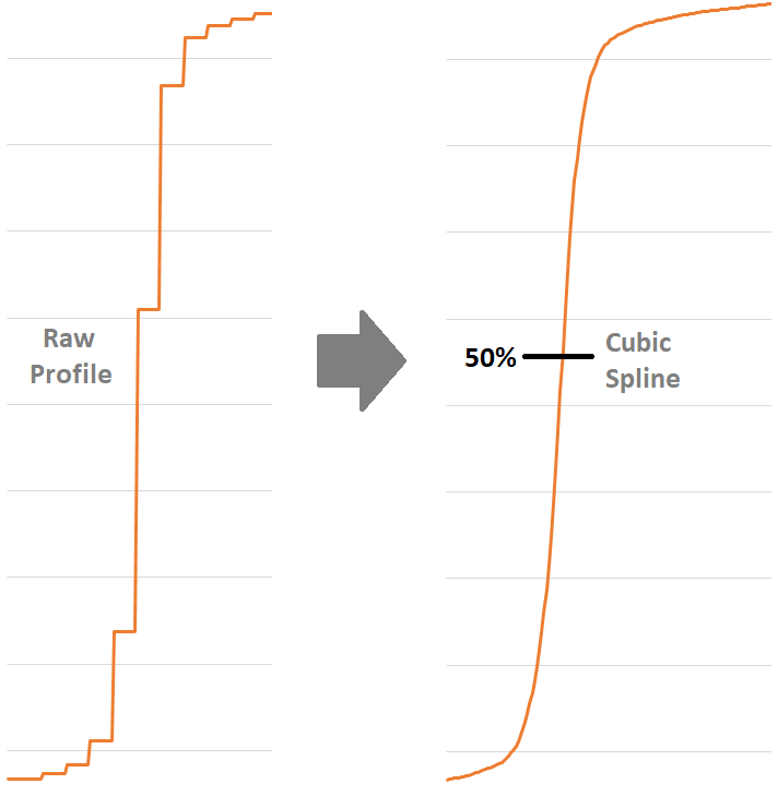
Using the cubic spline, a binary search which tries different horizontal inputs is used to find the vertical position where the curve is halfway ( 50% ) between the upper and lower bounds. The resulting horizontal position is used as the edge measurement.
Notes: